
Wiring & Pin-Out Reference
Wire colours and pin-outs for Spectre trackers, plus general installation diagrams for power, ignition, and relay wiring. Find the harness type that matches your unit below.
Last updated: 24/09/2026
Wire colours by harness type
Spectre Basic/Advanced
Cars, utes, vans — and heavier vehicles on the wide-voltage variant
5-pin wiring harness
Power +12/24 V DC (some units support up to 90 V for trucks & machinery)
Ground (GND)
Ignition (switched 12 V ACC)
Analog input (e.g. fuel level)
Relay trigger / immobiliser output
- Ignition — Ignition input — Yellow wire
- Analog in — Analog input — Grey wire
- Output — Open-collector output for relay control — White wire
White wire drives a relay coil. Wire via a normally-open relay so the circuit is live when the output is low (fail-safe).
Spectre Pro
Trucks and machinery with CAN bus integration
8-pin wiring harness
Power +12/24 V DC
Ground (GND)
Ignition (switched 12 V ACC)
Configurable digital or analog input
Configurable digital or analog input
Relay output / immobiliser
Relay output / auxiliary
Relay output / auxiliary
- Ignition — Ignition input — Yellow wire
- Input A — Configurable digital or analog input — Green w/ White stripe
- Input B — Configurable digital or analog input — White wire
- Output 1 — Relay output — Orange wire
- Output 2 — Relay output — Purple wire
- Output 3 — Relay output — Grey wire
Three open-collector outputs available. Wire the chosen output via a normally-open relay so the circuit is live when the output is low (fail-safe). Reserve Output 1 for immobiliser by convention so 2/3 are free for aux loads (siren, lock, etc.).
This unit also reads vehicle CAN bus data where supported — no extra wiring needed for that. Leave any unused wires from the harness disconnected.
Plug-and-play (no wiring)
Plugs straight into your vehicle's diagnostic port
OBD-II port (J1962)
This unit has no digital outputs — choose a harness-based unit if immobiliser functionality is required.
Power, ignition detection, and vehicle data are all delivered through the OBD-II connector — no external wiring required. Takes under a minute to fit.
Not sure which one you have?
Power (typically +12–30 V DC)
Ground (GND)
Ignition signal
The colours above are the most common convention, but yours may differ. Contact support with a photo of your unit's label and we'll confirm the exact wiring for your device.
Installation diagrams
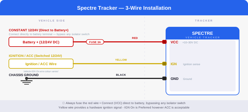
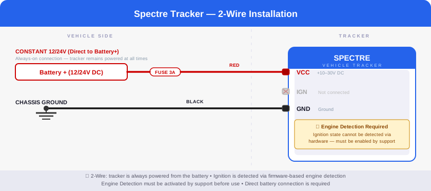
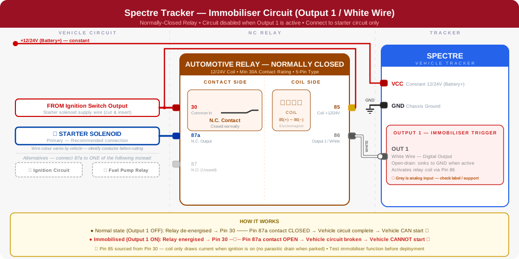
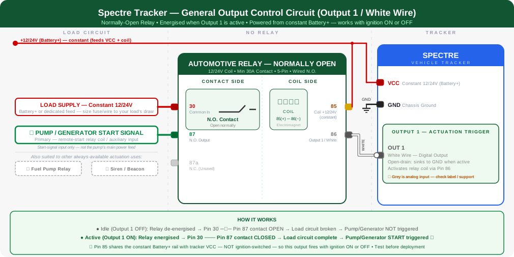
These cover the general wiring concepts for harness-based units — the circuit shape is the same across both harness types above, only the exact wire colours differ (see the tables above). Plug-and-play units need none of this.
Accessory note — OBD-II Bluetooth dongle
Mount the dongle within about 50cm of the tracker unit. Bluetooth range is short, and anything further can cause dropped connections or unreliable data. If the vehicle's OBD-II port sits far from where the tracker is hidden, run an OBD-II extension cable to bring the dongle closer instead of relying on distance alone.
Prefer not to DIY? Get in touch and we'll connect you with a local installer, or see the full FAQ & installation guide.